


Optical components are linked to the building through mechanical mounts and supporting frames. The beam path is not constant, and the beam direction frequently changes because the building is vibrating, the room temperature is changing, and the air is constantly moving. Tracking the beam path may minimize pointing errors at the focal spot location and avoid having the beam running outside the optical components. Alignment is a process that can be split into two parts: the static part (implementing highly stable devices) and the dynamic part (tracking beam path).
Static process
A large part of the error budget is dedicated to vibrations (of the building and of the mechanical frames) and to beam drift (air turbulence and temperature changes) that might occur after alignment is completed. This error budget is translated into a stability allocation for every component. For measurements of the location of the component, the front surface and its normal are given as the co-ordinates O(xo, yo, zo) and A(xa, ya, za). See Figure 1.
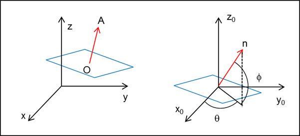
Figure 1: Left: Co-ordinates of the normal vector of a surface in the reference frame. Right: the same in the local frame where the normal vector is given as cylindrical co-ordinates (q, f).
One possible solution is to start from the computer-aided design (CAD) three-dimensional model where the locations of the components are known. These locations are then transferred to an Excel sheet. From this sheet, an optical baseline can be built at one of the following levels: a one-dimensional model with matrix laboratory (MATLAB), select nonlinear optics (SNLO) or Gaussian beam propagation (the LASCAD model), a ray-tracing code including diffraction effects (such as ZEMAX’s, for example), and the BPM including nonlinear effects with diffraction through FFT.
Dynamic process
There are two main processes: beam centering and beam pointing.
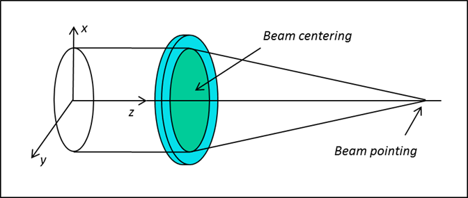 Figure 2: The final goal where the beam (green disk) is centered inside the optical component (blue disk) and where the beam direction is along the optical axis.
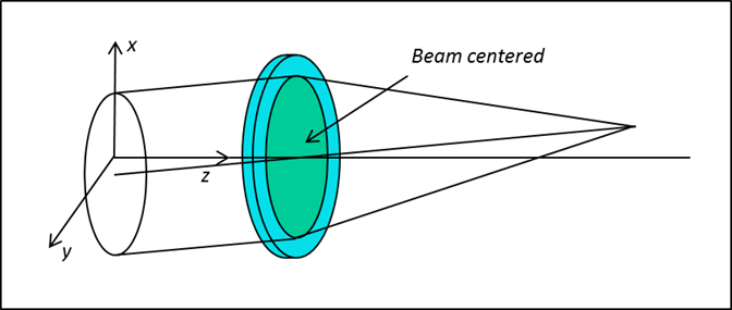 Figure 3: The beam (green disk) is centered inside the optical component (blue disk), but the beam direction is off axis.
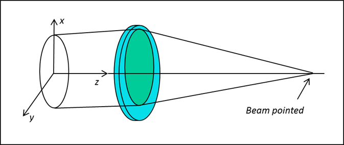
igure 4: The beam direction is along the optical axis, but the beam (green disk) is not centered inside the optical component (blue disk).
In both cases, the process is divided into three steps: defining a reference frame, defining an optical axis, and minimizing the distance between the two. For example, auto collimation can be performed in some cases but is not suitable when dealing with plane and parallel plates or mirrors.
Image generation and image processing
In order to detect a signal, it is necessary to have an object and a source of light. With an additional optical system, the image of this object can be detected by a CCD camera. An object can be a phase mask inserted in the beam to detect simple shapes such as a mask with a central circle to define the beam center or a mask with two circles on a vertical (horizontal) line to define a vertical (horizontal) axis. Light can be generated by multiple devices, either low-power CW lasers or fiber-coupled diode lasers. Alignment is based on video images of alignment references and beams. The system-wide video network supports the necessary levels of monitoring by operators as well as automated control by the control system.
Alignment system requirements
- The near-field centering tolerance throughout the system is ± % of the beam size.
- The far-field pointing tolerances range from mrad (5% of the smallest pinhole diameter) to/10 mrad at the output of the beam line.
- The final alignment requirement is to position each beam to its designated location in the target plane to within mm rms.
- Alignment tasks must be completed in seconds, minutes, or hours.
- A detailed error budget for the alignment system leads to accuracy requirements ranging from 0.5 to 2 pixels in various alignment loops.
